Showing posts with label 16f84a. Show all posts

Saturday, March 15, 2014

The Blinker in C

We are going to write our first program in C language, using MikroC compiler. It's not a free compiler, but we can use it for free upto some level.


 First, download the compiler and install it properly. Then create a new project and save it.  Select your microcontroller and clock speed properly. In this case, I'm using a PIC16f877A with a 8MHz clock.
 PIC16f877A with a 8MHz clock.
 
Then, type the following code in the text area you get, and then save it. This progra will switch on all the LEDs connected to port D once per second and then switch them off.
 
Pin connection
 
Code:
 
void main( )  {

         TRISD=0x00;             // make all the pins of PORTD output
         PORTD=0x00;           // make all the pins 0
 
 
         while(1) {                   // create an endless loop
                           PORTD=255;      //switch on all LEDs
                           Delay_ms(1000); //wait for 1s
                           PORTD=0x00;    //swithc off ann LEDs
                           Delay_ms(1000);  // wait for another 1s
                        }      // end of while(1)
 
       }  // end of the main program
 
 
Write the code and compile it by clicking the build button. Then you can simulate the code using Proteus ISIS or directly program it to the PIC microcontroller.


Saturday, December 14, 2013

PIC16 - Registers and Ports

Registers

Registers are the places where we store data inside the microcontroller. We can read stored data whenever required. So we can say that, registers act as small note books where we write data and read from.


Internal registers of PIC16F84A


Above figure shows the internal arrangement of registers of pic16F8x family. You may observe that the registers are divided into two banks, Bank 0 and Bank 1. Bank 0 is used for data operations. Bank 1 is used to control the (physical) operations of the microcontroller.

There are three important registers that we have to get familier with.

STATUS register

We use this register to switch between Bank 0 and Bank 1, by changing the 5th bit. To change from Bank 0 to Bank 1, we set the bit 5 to 1. To change from Bank 1 to Bank 0, we set the bit 5 to 0.
The STATUS register is located at the address 03H. (This is a hexadecimal value. "H" stands for hex.)

TRIS registers (TRISA/TRISB)

TRIS registers defines the direction of a port or a pin. If we set a bit in TRISA to 0, corresponding bit of PORTA will become an output. If it is 1, corresponding pin of the port will be an input. (What to remember is, 1=input  and  0=output )

PORT registers (PORTA/PORTB)

Port registers simply reffer to the I/O ports. The number of I/O ports depend on the microcontroller. PIC16f84A has two I/O ports which are namely PORTA and PORTB.

Pinout of a PIC16F84A

PORTA has 4 pins, pin 17, 18, 1 and 2 respectively. PORTB has 8 I/O pins, from pin 6 to 13.

well, that is a brief introduction on Registers and I/O ports. There are so many other ports and registers, which change from one device to another. In our next post, let us discuss how to send values to ports or registers.

Friday, August 30, 2013

The Blinker - My first Assembly language program


In my previous post, I gave you a brief introduction to PIC 16f84A microcontroller. There’s a lot more to cover before moving on to programming section. But, I have decided to show you a simple assembly program, just to keep you guys interested in this topic and to understand the basic concepts. It will blink two LEDs as in an LED robot circuit.
To write and run this program, you’ll need the following softwares.
  • MPLAB IDE- a free assembly language compiler provided by Microchip, the manufacturer of PIC microcontrollers.
  • Proteus ISIS- to simulate your program before going to hardware level.
Follow these steps after downloading the required softwares.
1. Install MPLAB IDE.
2. Go to File>>New.
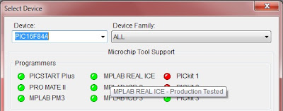
3. Go to Configure>>Select Device and select PIC16F84A.


   4. Type(or copy) following assembly code into the code window. Don’t worry if you don’t understand the code.
 ;;;;;;define registers;;;;;;;  
 STATUS equ 03h  
 TRISA   equ 85h  
 PORTA  equ 05h  
 COUNT equ 08h  
 ;;;;;;configure I/O ports;;;;;;;  
 bsf  STATUS,5  
 movlw 00h  
 movwf TRISA  
 bcf  STATUS,5  
 ;;;;;;Turn LED1 on,LED2 off;;;;;;;;;;  
 Begin movlw 01h  
       movwf PORTA  
 ;;;;;;Call the delay;;;;;;;  
 call Delay  
 ;;;;;;Turn LED1 off,LED2 on;;;;;;;;  
 movlw 02h  
 movwf PORTA  
 ;;;;;;Call Delay again;;;;;  
 call Delay  
 ;;;;;go back to the beginning;;;;;;  
 goto Begin  
 ;;;;;Delay subroutine;;;;;  
 Delay  
 Loop decfsz COUNT,1  
       goto Loop  
 return  
 ;;;;;end of program;;;;;  
 end  
5. Save it somewhere in your hard drive as “firstprog.asm”. Remember this location.
 
6. Now, go to Project>>Quick Build(firstprog.asm)
If you have followed so far properly, you should get a message which says “BUILD SUCCEEDED”. Now you have successfully compiled your program.
You’ll find a file named firstprog.HEX, where you have saved the program code. It is the firmware which we place in the PIC microcontroller. Now we are ready to do a simulation of the program.

Simulation

1. Download Proteus ISIS and launch it.
2. Click on “Component mode” icon at the left corner and double click on the white area under “Devices”.
3. Then, you can search and select any device you want. In this case, we need 2 LEDs and one PIC18F84A microcontroller. Type the microcontroller number in the search box. The results will be displayed in the field to the right. Double click on the selected component, so it would be added to your list of devices.
4. Design the circuit as shown in the following picture.(Check the Youtube video below)
5. Double click on the PIC16F84A and locate the firstprog.HEX file.
6. The Blinker is now ready to run. So finally, hit the “play” button in the bottom left corner of the screen to begin the simulation.

If everything goes alright, The Blinker will start blinking, one LED at a time.

Wednesday, August 28, 2013

Introduction to PIC microcontrollers


Hello everyone. I’m going to start a new tutorial series on pic programming, which could be very useful for beginners. First, I wish to give a brief description on microcontrollers and then move on to the next section, PIC16f84a programming using C language. Once you have understood the basics of the PIC, let’s move on to PIC18 series.

What is a microcontroller?

PIC18F8720 microcontroller


In brief, microcontroller is a kind of a small computer, packed in a small IC. Think of an ordinary computer for an instance. They come with a RAM, ROM, CPU, Hard drive, Input/Output devices, ports and a mainboard to connect them all together. In a microcontrollers also, all those things are there, but they are built in and sealed. So it’s not possible to change hardware configurations as we wish.

Applications of microcontrollers


Microcontroller based systems
Nowadays, there are microcontroller based systems in almost all of the electronic appliances. They are there in TV sets, DVD players, microwave ovens and everything. Even the remote controller of a TV or the LCD display of a microwave oven are driven by microcontrollers. So it’s very important for any IT/ electrical/electronic professional  to have a good knowledge about these devices.

PIC16F84A Microcontroller


PIC16F84A microcontroller
 
This is a small microcontroller, manufactured by “Microchip”, one of the leading semiconductor manufacturers. There are 18 pins, arranged as 9 in a side.

PIC16F84A pinout
 

PORTA(RA0 to RA4)

PortA or RA is an I/O port, which could be used as an input or as an output. The port has 5 pins, so it could work as a 5 bit port, where the bit numbers are from RA0 to RA4.
 

PORTB(RB0 to RB7)

PORTB also similar to PORTA, except the fact that it has 8 bits.

OSC1 and OSC2(CLK IN and CLK OUT)

An external oscillator is connected to these pins. (In this case, we wish to use a 4MHz crystal oscillator.)

VSS, VDD and MCLR

VSS is the positive power supply of the PIC. VDD is the negative power supply pin. MCLR is used when we program the PIC microcontroller. However, it is normally connected to the positive power supply pin using a resistor.

INT

INT pin is used to get a special input called “interrupts” . More on this pin comes later.

If you don’t get any of these things, just relax. You’ll understand everything when we start to write programs, which means from next post onwards.
Got any doubts? Feel free to post a comment. I’ll reply ASAP.