Tuesday, February 13, 2018

Fix for HC-06 connection problem with Windows 10

Many people, including myself, have used HC-06 with many earlier versions of Microsoft Windows, such as Windows Vista, 7 and 8 without any problem. The HC-06 module did it's job happily and the Bluetooth Serial link was very reliable. I have used it in many applications where I had to hook up a device with Serial Communication to my PC, just to get rid of the trouble of using long wires. I once made it to work as a wireless communication gateway to monitor a marine engine that came with a serial communication interface, which worked extraordinarily well between the engine room and the cabin.
However it all came to an end with the release of Windows 10, as all good things come to an end at one point. As Windows 10 prefers BLE communication, it became almost impossible for HC06 to get connected with a Bluetooth Serial port. It gets paired alright, but fails to be listed as a Bluetooth Serial connection.


However, after an years effort I realized that the following simple fix could solve this issue without any struggle.

The Issue 

The issue could be summarized as below.
  • HC-06 gets paired with windows 10.
  • Cannot add a Bluetooth Serial Port for the device
    • HC-06 is not listed in the device list
  • Bluetooth Serial port does not show up in the terminal software

The fix

This is not an uncommon issue. The same issue has occurred with many other Bluetooth devices including the HC-06 transceiver module and the good people at Microsoft must have heard of it through different error reports. As a result, it is most likely that the manufacturer of your PC's Bluetooth radio has released a driver update that will fix this issue. They have done so, in my case.

  1. Update the Bluetooth Driver
    • Try to find the update from the manufacturer's website directly.
    • If  the above step is not successful, the driver could be updated using windows update service.
  2. Restart the PC
    • Restarting all the services helps.
  3. Pair the device again, and add a Bluetooth serial port.

Check the drop-down menu for our module

Only the Outgoing port is useful for HC-06

Once the port is added, it will be visible in any Terminal software.

Bluetooth Serial port is available


Hello from Arduino (Over HC-06)


So after just a simple driver update, HC-06 Bluetooth Serial communication on Windows 10 works well, at least for me.

My OS Version is Microsoft Windows 10 Pro. Find version info from the below image.

My Windows version info

I cannot guarantee that this will work for everyone, but it did for me. So it's worth a try, as it would only cost you a few minutes and a few megabytes of data.

I am Dilupa Herath. 
You can reach me on Whatsapp (+94 77 45 45 624) 
or by email (dilupaherath1990@gmail.com)


Saturday, February 10, 2018

Connecting Arduino to Android with HC-06 Bluetooth module

HC-06 Bluetooth module

Many of my colleagues and friends often ask me help on connecting their Arduino boards with Android apps, so that they could control external devices using their smartphones. For this task, I always recommend the HC-06 Bluetooth slave module. It is cheap, reliable and does the job with a minimum setup.  

How does it work?

HC-06 works as a UART to Bluetooth radio, which broadcasts whatever the data read from the UART interface, and vice versa. Therefore, no special commands are required to communicate over Bluetooth using HC-06. It will simply transmit the data sent to it by using Arduino's Serial.print() function.

Hooking up HC-06 with an Arduino UNO


Getting Started: The Android app

To get started, I recommend using the Bluetooth Control for Arduino from Play Store. This app provides a good interface to control digital outputs.


Each of the four large buttons on the front screen of this app could be used to turn on and off four digital output pins separately.  When each button is pressed for the first time, they will send out the characters '1', '2', '3' and '4' respectively. When the are pressed again, the characters 'A', 'B','C' and 'D' will be sent out respectively.
The first set of characters could be used to turn on the outputs, and the second set of characters could be used to turn them off. 

Getting Started: The Arduino code


 #include <SoftwareSerial.h>  
 SoftwareSerial mySerial(10,11); //Software Serial, RX=pin 10, TX=pin 11  
   
 const int output1=3;  
 const int output2=4;  
 const int output3=5;  
 const int output4=6;  
 String input;  
   
 void setup() {  
  Serial.begin(9600);  
  mySerial.begin(9600);  
  pinMode(output1,OUTPUT);  
  pinMode(output2,OUTPUT);  
  pinMode(output3,OUTPUT);  
  pinMode(output4,OUTPUT);  
 }  
   
 void loop() {  
  while(mySerial.available()) {   //read the serial input  
   input += (char)mySerial.read();  
   delay(5);  
  }  
  if (input.length()>0) {   //if the input is not empty  
   setOutputs(input);    //call the setOutputs function  
  }  
  input="";  
 }  
   
 /*set Outputs according to the inputs*/  
 void setOutputs(String input){  
  if(input.indexOf("A")>-1)  
   digitalWrite(output1,LOW);  
  else if(input.indexOf("B")>-1)  
   digitalWrite(output2,LOW);  
  else if(input.indexOf("C")>-1)  
   digitalWrite(output3,LOW);  
  else if(input.indexOf("D")>-1)  
   digitalWrite(output4,LOW);  
   
  else if(input.indexOf("1")>-1)  
   digitalWrite(output1,HIGH);  
  else if(input.indexOf("2")>-1)  
   digitalWrite(output2,HIGH);  
  else if(input.indexOf("3")>-1)  
   digitalWrite(output3,HIGH);  
  else if(input.indexOf("4")>-1)  
   digitalWrite(output4,HIGH);  
  }  

This code will turn on and off four LEDs attached to digital pins 3, 4, 5 and 6. They could be replaced with relays to control devices that requires AC mains to operate. Eventhough there are other complex methods to get this task done, this simple method is useful as it keeps things simple and does its job well.

Monday, February 5, 2018

Reading Arduino Inputs to a Binary Number


In one of my recent projects, I had to read a few digital inputs of an Arduino board into an integer variable as a binary number. My initial thought was to use direct register addressing, but later on, I came up with two other methods which work really well. Here on my blog, I share all three of them, hoping that these would help someone else as well.

Note: Pull down resistors MUST be used for each example.


1. Only using digitalRead()
 void setup() {  
  Serial.begin(9600);  
  pinMode(2,INPUT);  
  pinMode(3,INPUT);  
  pinMode(4,INPUT);  
  pinMode(5,INPUT);  
 }  
 void loop() {  
   int b0 = digitalRead(2);  
   int b1 = digitalRead(3);  
   int b2 = digitalRead(4);  
   int b3 = digitalRead(5);  
   int output=b0+(2*b1)+(4*b2)+(8*b3); //create the binary number  
   Serial.println(output);  
   delay(100);  
 }  


2. Using BitShiftLeft (<<)

 void setup() {  
  Serial.begin(9600);  
  pinMode(2,INPUT);  
  pinMode(3,INPUT);  
  pinMode(4,INPUT);  
  pinMode(5,INPUT);  
 }  
 void loop() {  
   int b0 = digitalRead(2);  
   int b1 = digitalRead(3);  
   int b2 = digitalRead(4);  
   int b3 = digitalRead(5);  
   b1=b1<<1; //Shift the second bit by one binary place  
   b2=b2<<2; //Shift the third bit by two binary places  
   b3=b3<<3; //Shift the fourth bit by three binary places  
   int output=b0+b1+b2+b3; //add them together  
   Serial.println(output);  
   delay(100);  
 }  


3. Reading the registers directly - Simplest method so far

In AVR microcontrollers, there is a register called Chip Register, which stores the input value of a particular group of pins (a port). In This example, Chip register is read and assigned directly to an int variable.

 void setup() {  
 Serial.begin(9600);  
 }  
 void loop() {  
 DDRC=0x00; //Set all the pins of PortC to be inputs (A0 to A5 on Arduino Uno)  
 int a=PINC; //Read the input pins directly into a binary number   
 Serial.println(a);  
 delay(500);  
 }  


This last code is amazingly simple, and lightweight.  It could be way more useful when combined with Arduino Core functions. 

Wednesday, October 21, 2015

Read data from a CSV file in C#


In my previous post, I have shared a simple code to create CSV files and to append data to the same file. In this one, I will share a simple method to read data from a CSV file.

Note: This code will read everything as Strings. But there are so many built-in functions in Visual Studio to convert Strings to any other data type.


 using System;  
 using System.Collections.Generic;  
 using System.ComponentModel;  
 using System.Data;  
 using System.Drawing;  
 using System.Linq;  
 using System.Text;  
 using System.Threading.Tasks;  
 using System.Windows.Forms;  
 namespace WindowsFormsApplication3  
 {  
   public partial class Form1 : Form  
   {  
     public Form1()  
     {  
       InitializeComponent();  
     }  
     private void button1_Click(object sender, EventArgs e)  
     {  
       System.IO.StreamReader reader = new System.IO.StreamReader(System.IO.File.OpenRead(@"D:\WriteData.csv"));  
       while (!reader.EndOfStream)  
       {  
         string line = reader.ReadLine();  
         textBox1.Text += line;  
         textBox1.Text += "\r\n";  
       }  
     }  
   }  
 }  

My Windows Form with a text box and a command button

Once the "Read CSV file" button is pressed, the content will be read line by line, including the commas.


Creating a CSV file with C#

I came across an interesting project that some of my friends are working on, which requires them to capture some data received from the serial port and to log them into a CSV file. Giving some thought about the requirements, it occurred to me that this task could be easily get done by using C# or VB.NET.

After doing some research, I found so many complicated methods of creating CSV files and appending data into them. However, I found this extremely simple way to do the same task somewhere on the StackOverflow, and decided to give it a go.

The basic idea here is to convert all the received data into strings, and to store them in a string array. After that, they could be written into the CSV file using native File  Write commands. I have designed a simple windows form with one command button in it for writing data to the CSV file.


Click me to create the CSV file!!

This code is tested on Microsoft Visual Studio 2015. It creates a CSV file on the drive D.


 using System;  
 using System.Collections.Generic;  
 using System.ComponentModel;  
 using System.Data;  
 using System.Drawing;  
 using System.Linq;  
 using System.Text;  
 using System.Threading.Tasks;  
 using System.Windows.Forms;  
 namespace WindowsFormsApplication2  
 {  
   public partial class Form1 : Form  
   {  
     public Form1()  
     {  
       InitializeComponent();  
     }  
     private void button1_Click(object sender, EventArgs e)  
     {  
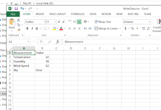
       string[] lines = { "Measurement, Value",  
                 "Temperature ,32",  
                 "Humidity , 78",  
                 "Wind Speed , 12",  
                 "Sky,Clear"  
                };  
       System.IO.File.WriteAllLines(@"D:\WriteData.csv", lines);  
     }  
   }  
 }  

The resultant CSV file on my local drive D 


However, this code does not append new data to the CSV file. Instead, it overwrites the data in the CSV file at each button press. To append data, use "System.IO.File.AppendAllLines".

     private void button1_Click(object sender, EventArgs e)  
     {  
       string[] lines = { "Measurement, Value",  
                 "Temperature ,32",  
                 "Humidity , 78",  
                 "Wind Speed , 12",  
                 "Sky,Clear"  
                };  
       System.IO.File.AppendAllLines(@"D:\WriteData.csv", lines);  
     }  

By combining this code with the built in serial communication functions, one could easily get the above mentioned task done.

Saturday, March 15, 2014

The Blinker in C

We are going to write our first program in C language, using MikroC compiler. It's not a free compiler, but we can use it for free upto some level.


 First, download the compiler and install it properly. Then create a new project and save it.  Select your microcontroller and clock speed properly. In this case, I'm using a PIC16f877A with a 8MHz clock.
 PIC16f877A with a 8MHz clock.
 
Then, type the following code in the text area you get, and then save it. This progra will switch on all the LEDs connected to port D once per second and then switch them off.
 
Pin connection
 
Code:
 
void main( )  {

         TRISD=0x00;             // make all the pins of PORTD output
         PORTD=0x00;           // make all the pins 0
 
 
         while(1) {                   // create an endless loop
                           PORTD=255;      //switch on all LEDs
                           Delay_ms(1000); //wait for 1s
                           PORTD=0x00;    //swithc off ann LEDs
                           Delay_ms(1000);  // wait for another 1s
                        }      // end of while(1)
 
       }  // end of the main program
 
 
Write the code and compile it by clicking the build button. Then you can simulate the code using Proteus ISIS or directly program it to the PIC microcontroller.


Saturday, December 14, 2013

PIC16 - Registers and Ports

Registers

Registers are the places where we store data inside the microcontroller. We can read stored data whenever required. So we can say that, registers act as small note books where we write data and read from.


Internal registers of PIC16F84A


Above figure shows the internal arrangement of registers of pic16F8x family. You may observe that the registers are divided into two banks, Bank 0 and Bank 1. Bank 0 is used for data operations. Bank 1 is used to control the (physical) operations of the microcontroller.

There are three important registers that we have to get familier with.

STATUS register

We use this register to switch between Bank 0 and Bank 1, by changing the 5th bit. To change from Bank 0 to Bank 1, we set the bit 5 to 1. To change from Bank 1 to Bank 0, we set the bit 5 to 0.
The STATUS register is located at the address 03H. (This is a hexadecimal value. "H" stands for hex.)

TRIS registers (TRISA/TRISB)

TRIS registers defines the direction of a port or a pin. If we set a bit in TRISA to 0, corresponding bit of PORTA will become an output. If it is 1, corresponding pin of the port will be an input. (What to remember is, 1=input  and  0=output )

PORT registers (PORTA/PORTB)

Port registers simply reffer to the I/O ports. The number of I/O ports depend on the microcontroller. PIC16f84A has two I/O ports which are namely PORTA and PORTB.

Pinout of a PIC16F84A

PORTA has 4 pins, pin 17, 18, 1 and 2 respectively. PORTB has 8 I/O pins, from pin 6 to 13.

well, that is a brief introduction on Registers and I/O ports. There are so many other ports and registers, which change from one device to another. In our next post, let us discuss how to send values to ports or registers.